Хорошо что есть старшие товарищи , на их опыте мы экономим и деньги и время, столько кабелей нет не в одном салоне города как у тебя, скоро они будут брать на прослушку твои прогретые…
2 лайка
У usb толерантность к джиттеру довольно большая. До 25%. Поэтому если отклонение уложится в эти требования бит будет правильный.
На usb.org есть спецификации протокола. В разделе 7.1.2.2 есть шаблоны глазковых диаграмм.
Здесь важно понять как происходит процесс распознавания 0 и 1. Он происходит не как в компьютере логической операцией, а по нарастанию напряжения. Как только достигнуто нужное значение значит единица, ниже определенного значения - ноль.
Это как очередь из металлических шариков в трубке. Есть моторчик который загружает новый шарик тем самым продвигая остальные. Но движение идет непрерывно. Фапч просто синхронизирует второе устройство с тем потоком который поступает. Если подающий мотор чуть подклинивает, то образуются зазоры. Если зазор в пределах допуска, то всё работает.
Вообще usb изначально рассчитан на взаимодействие большого количества разных устройств, поэтому допуски у него не маленькие.
С абсолютностью первой части утверждения не согласен, что надо начинать с “с питания и ethernet, если он используется”.
А вот вторая часть “Если же стоит задача…” - правильная ) Надо начинать с целеполагания, именно оно фундамент. Про питание и т.п. - уже задачи отдельные. Т.е. продолжая мой пример выше, если цель стоит получить удовольствие от прослушивания музыки, большинству не надо заботиться о питании. До этих глубин, как в вашем случае еще надо докопаться, чтобы подобные факторы стали действительно важны для достижения цели.
В добрый путь… 
Понимание того, что звук в основном зависит от характера взаимодействия аппаратов системы между собой и от их реакции на внешние факторы у многих кого-то может и не появится вовсе.
1 лайк
То есть с потенциальной проблемой связанной с возможной некорректностью передачи цифровых данных, которая не детектится bitperfect разобрались, ее не существует, правильно? При тесте ЦАП знает какой файл д.б. на входе, если в очередном пакете приходит сбойная информация - понимает, что это не bitperfect.
Соответственно чтобы исключить подобные сбои в реальных условиях достаточно промониторить стабильность bitperfect-ности потока.
Единственной мумба-юмбой которая потенциально может оказывать на итоговый звук непонятное влияние остается связь электрическая источника с ЦАПом.
Верно?
Самой главной, на мой взгляд, “мумба-юмбой” для цифровой передачи аудио является точность часов и то как их передают.
Если допустить что у нас идеальное тактование (а в большинстве аппаратов совсем не идеальное) то проблемы формируются на этапе передачи сигнала. Причем можно рассматривать не только систему состоящую, например из компьютера и ЦАПа с usb входом, но и систему внутри ЦАПа от usb приемника до собственно микросхемы ЦАП.
Это она и есть - тайминг. Битперфект считает биты, а точность их прихода не считает.
2 лайка
Согласовав аппараты между собой, перестал слышать большую разницу в классе между источниками разного уровня. Сначала даже напрягся немного 
1 лайк
Есть сильная зависимость от устойчивости каждого аппарата, каждый реагирует по-своему, а если им ничего, ну, или почти ничего не мешает, то… музыка-то одна.
Хотя на мой взгляд разница довольно большая между всеми, но не такая, что музыку мешает слушать.
По-моему по кругу пошли. Мы рассматриваем асинхронную передачу. И если нет глобального заговора индустрии и вместо асинхронного взаимодействия нам впаривают синхронное - то что вы выше пишете про распознавание 0 и 1, про шарики в трубке - по приходу в ЦАП должно детектиться как bitperfect / не bitperfect, всё ли из исходного файла успешно добежало до ЦАПа (а по всему смыслу асинхронности воспроизводятся не мгновенно, поэтому да - зазор для “шариков” не влияющий на результат USB очевидно может себе позволить) - в этом очевидно смысл теста. Или что в утверждении этом упущено, чтобы закрыть вопрос с обсуждением этой части? )
Про необходимость максимизации качества ЦАПа я был исходно всецело согласен.
Действительно, по кругу.
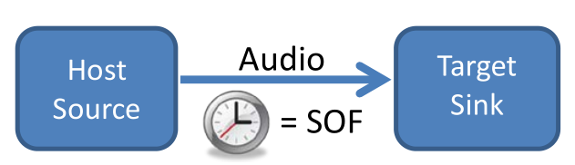
Истинно асинхронную передачу обеспечивает Bulk Transfer Mode. Изохронный режим “привязан” к синхронизации по сигналу SOF (Start Of Frame).
1 лайк
Именно по кругу )) Т.к. нет однозначного соответствия технических и аудио терминов. Асинхронность USB здесь аудио термин, а не конкретная реализация в терминах USB (знаем, что может подразумеваться и bulk и изохронный режим в реализации).
И кстати видел несколько раз, что под “асинхронным USB” для аудио понимают синхронизацию со стороны аудио-девайса, а на источника при передаче (видимо продукт натягивания “совы на глобус” - пропиаренного термина “асинхронный USB” на изохронную реализацию). Собственно, когда передачей рулит ЦАП (в подходе pull, а не push) логика приведенная мной выше с битперфектностью как методом контроля корректности и завязанностью на качество ЦАП в первую очередь такой вариант только усиливает.
Кстати вот, у NAIM V1 например такое определение:
Asynchronous mode USB
Asynchronous mode is superior to other USB data
transfer modes because it allows the DAC to control
the flow of audio data rather than the computer. Data
is ‘pulled’ from the computer under control of the DAC,
not ‘pushed’ to the DAC under control of the computer.
This allows a high precision, low phase noise clock to
be placed optimally, close to the digital-to-analogue
converter chips, thereby ensuring the lowest possible
output jitter and best possible sound quality.
Похоже, что конкретная реализация приемника ограничивается контролем переполнения/опустошения буфера (см. сообщение #60 текущей ветки).
Frequency stability – or, you guessed it, the lack of it
If your USB replay device is running in adaptive or synchronous mode, it needs to create the clocks that the D/A converter will require. For a regular audio DAC, the most likely value for this clock frequency is 256 times the audio sampling frequency. All USB audio interface approaches running in these modes have some sort of adjustable oscillator, and in microcontroller-based systems this oscillator is usually digitally controlled, in firmware. There’s usually a finite, quite coarse resolution, to the frequency setting.It’s quite common for microcontrollers to have some sort of programmable oscillator whose frequency is joggled about to ensure that the mean oscillator rate is set to what you want. You’ll use this to keep track of your FIFO read and write pointers and change the duty cycle of your pointer joggling in a way that holds the gap between them reasonably constant (this is Adaptive mode at work, pushing the CPU hard). This joggling clock is used as the master clock for the DAC, and also to shift data across the interface between the microcontroller and the DAC.
Now imagine that you’re reproducing a nice accurate sinewave. Let’s say that the frequency of that sinewave should be exactly 1.4 kHz (a favourite frequency – 1 kHz is pretty useless when working with USB audio systems) when the DAC is fed samples at exactly 44,100 per second (the most standard of the digital audio sampling rates, because it’s the value used on CDs).
But what if you’re toggling your master oscillator between two frequencies, such that the system spends half its time replaying at say 44,250 samples per second and the other half at 43,950 samples per second. For sure, the mean replay rate is 44,100 samples per second. But actually, the system spends half of its time sending out a sinewave at 1.40476 kHz and the other half of its time at 1.39524 kHz.
For anyone out there who thinks “Hmm, doesn’t seem so bad,” consider this: such a level of pitch shift is considered to be audible to a perfectly average listener – let alone the so-called “golden ears” of the audio industry. And in case you think these are just some ridiculous numbers picked to make a point, look at figure 5, measured off the dev kit of a microcontroller vendor.
Figure 5: The average frequency is correct, but the variation is audible.

Так этот как раз момент аудиофильское определение “Asynchronous USB” и забарывает в первую очередь.
Идем обратно от этой посылки.
Если используется клок ЦАПа, то источник не имеет возможности в 1 секунду в понимании ЦАПа напихать больше или меньше сэмплов, ЦАП в свое определение секунды получает именно нужное количество.
Забавная это опора на теорию.
Бегал с асинхронным USB как с панацеей в 2008 году, отпустило. Чего и всем желаю.
In theory, there is no difference between theory and practice; in practice, there is.
1 лайк
Предлагается опираться исключительно на практику с методикой сравнения “жена с кухни прибежала”? Что-то других примеров сравнений не приводилось пока ) В таком подходе можно рандомно очаровываться и разочаровываться вне зависимости от реально присутствующих или отсутствующих различий в звуке…
(Ну и напомню, что ветка так то про аудиоплееры ))
1 лайк
Ключевой момент
Полностью независимое тактирование реализуется лишь при асинхронном режиме. Приведенный выше пример, разумеется, утрированный, но основной посыл ясен. Если же рассматривать ситуацию в условиях, приближенных к боевым, то стоит процитировать одного из разработчиков ECDesigns:
There are USB DACs based on isochronous or asynchronous USB audio transfer. Isochronous DACs recover the USB audio source clock using a PLL-based clock recovery system. This is -very- likely to cause USB audio source related jitter and interference issues as we don’t have access to a clean independent local clock signal. PLLs generate certain amount of jitter, the very best, used for this application produce approx. 50ps of intrinsic jitter. Jitter increases significantly during clock recovery. This isochronous setup will be highly sensitive to USB audio source and USB interlink properties.
Data corruption (there is no way of correcting data) seems to be a non issue. TI reported one error in an isochronous transmission every few weeks if I recall correctly.
Asynchronous USB DACs have a “clean” local masterclock that serves as DAC timing signal. The amount of data flowing from USB audio source to the asynchronous DAC is regulated in order to synchronize the USB audio source with the USB DAC. The advantage is that we now have some more control over clock signal quality.
So to sum things up we need following in order to improve USB audio performance:
- Ensuring playback is bit-perfect.
- Self powered DAC (USB audio source bus power is not used to power the DAC).
- Suitable galvanical insulation between both, USB audio source and DAC.
- Asynchronous USB audio DAC (local audio clock).
Ok all is fixed then, time for coffee,
Eh, no.
Let’s assume we did everything right (above list) and use an asynchronous XMOS USB audio receiver for example.
This is what is going to happen:
USB data plus interference on its amplitude plus timing fluctuations on its transients arrive at the DAC after struggling through a non-perfect USB interlink. The contained DATA is still clearly readable but the signal has become noisy.
This noisy serial signal enters a PHY de-serializer that feeds parallel DATA to the XMOS core’s. At this moment we polluted the receiver power supply and ground plane with USB audio source related interference.
Both, PHY and XMOS need clock signals to run, not just any clock signal, multiple of 13 MHz please. Let’s call this the -system clock-. The source interference crosstalks to this system clock and we have a modulated radio wave on our hands, it is modulated with source interference. Unless we use perfect screening, this interference is broadcasted and reaches each and every component in the DAC through EMI.
HF signals are not audible so why bother? The problem occurs when these modulated carrier waves get demodulated and then dump the contained audible interference right into the audio spectrum, like with a radio receiver. It only takes a single P-N junction to demodulate such amplitude modulated carrier.
Next we have some nice, low jitter masterclocks, the audio clocks. These are going to be used for our DAC timing signal …. somehow. But these will also receive EMI and the datasheet phase noise specs go down the drain.
This audio clock is either a multiple of 44.1 KHz or 48 KHz. So we basically require two audio clocks.
We could go for 22.5792 MHz and 24.576 MHz for example. The XMOS determines the incoming sample rate and selects the correct audio clock by means of a SEL signal. The XMOS produces interference too and the I/O pin enabling the masterclock output dumps this noise on the sensitive oscillator circuits through the clock buffer. The audio clock is not so clean annymore ….
The XMOS can only change the state of the I2S signals on it’s I/O pins when the -system- clock changes. The system clock frequency however is not an exact multiple of the -audio- clock. So things are not going to “fit” perfectly. After the audio clock changes state, there is a variable but specified guaranteed response time from the XMOS. This results in -very- high jitter on -all- I2S signals generated by the XMOS. This jitter is easy to measure with a spectrum analyser and even with an oscilloscope.
When we use these XMOS I2S output signals directly, we are rewarded by a truckload of jitter. Similar happens when using I2S outputs of a RaspBerrie pie for driving a DAC. If you want to have truckloads of jitter (timing) and interference (ripple) on the I2S signals, plus a nice ground loop, this is the way to do it.
This jitter is so severe that when generating a S/PDIF signal with the XMOS USB audio receiver, the connected S/PDIF receiver won’t even lock. So we are not talking about neglible jitter here as it causes data corruption with S/PDIF.
Because the variable response time is guaranteed (XMOS is a state machine processor), we can apply synchronous reclocking by using the -audio- clock once more. This comes with further increased phase noise levels through parastitics in the synchronous reclockers.
Jittery I2S signal -> D-flip-flop (clocked by the audio clock) -> “cleaned-up” I2S signal.
One -could- simply feed the jittery I2S signals into a DAC chip and pray that the DAC masterclock signal will cure all, somewhere deep inside that piece of silicon. In practice this is not going to work very well either.
One -could- add an extra FIFO buffer that collects I2S data from the XMOS and clocks it out with the audio clock. We basically applied synchronous reclocking while adding more unnecessary switching noise from the FIFO buffer components.
One -could divide-down the audio clock, generating BCK and or WS, but when the divider skips some pulses or starts at some random position we will end up with phase locking problems and related data corruption. On top of that we would also require a programmable divider for multiple sample rate support that in turn would have to be controlled by the XMOS.
So even a “simple” thing as “using the audio clock to clock the DAC” turns out to be rather problematic and there are different options that lead to different results.
In a perfect world with perfect parts we would have been able to block source jitter by synchronous reclocking and shield the circuits against EMI. We would have ground planes with zero impedance.
In the real world we have to accept degrading introduced by imperfect parts.
Here is a short list of frequencies (fundamentals / harmonics) produced by a single 24.576 MHz clock that would typically occur in a USB DAC, and related impedance of “only” 5pF stray capacitance:
24.576 Mhz, 5pF -> 1.29 K Ohms
49.152 Mhz, 5pF -> 647 Ohms
73.728 Mhz, 5pF -> 431 Ohms
98.304 Mhz, 5pF -> 323 Ohms.
122.88 Mhz, 5pF -> 259 Ohms.
147.456 Mhz, 5pF -> 215 OhmsThese “parasitics” are present between all pins of all chips used in a DAC. When added to the schematics we get a completely different picture of this truly -hopeless- situation. And these are only the parasitic capacitances, we also have parasitic inductance and coupling.
In our straight-forward XMOS USB receiver we already have 3 different oscillator frequencies plus harmonics, imagine what chaos this will produce in all parasitics present in a DAC.
-> The end result is a USB DAC that always sounds different, the sound changes with mains pollution, WIFI activity, CPU load (virus scanners, WAV/AIFF vs ALAC/FLAC, applicatios and so on), temperature (oscillator drift, parasitic capacitance change), humidity (high Ohmic bypass on the PCB), USB interlink properties and so on. All this despite bit-perfect playback.
This collection of “digital” crap in these bit togglers is so critical that the slightest microscopic change will already change its performance. Suitable measurements of all -relevant- parameters would back this up. In my humble opinion we haven’t even identified all major DAC parameters responsible for -perceived- sound quality yet.
У меня никто не бегает.
Но я и перетыками не сравниваю, конечно.
1 лайк
Это кстати как установить? Опять двойные слепые перетыкания, для мучения аудиофилов и на потеху Сталкеру?
1 лайк
Молодца чувак, умеет продавать ) Остается только недоумевать - как после таких ужасов USB ЦАП на клочки не разрывает )) А! Понял, именно для этого из цельного слитка люминия корпуса и вытачивают )
Ну а если серьезнее, против посыла ниже и не было возражений, что по электричеству источник может гадить в ЦАП. Вопрос только в реальном объеме этого влияния на результирующий звук.